
How is the Pick and place machine working for SMT assembly
How is the Pick and place machine working for SMT assembly?
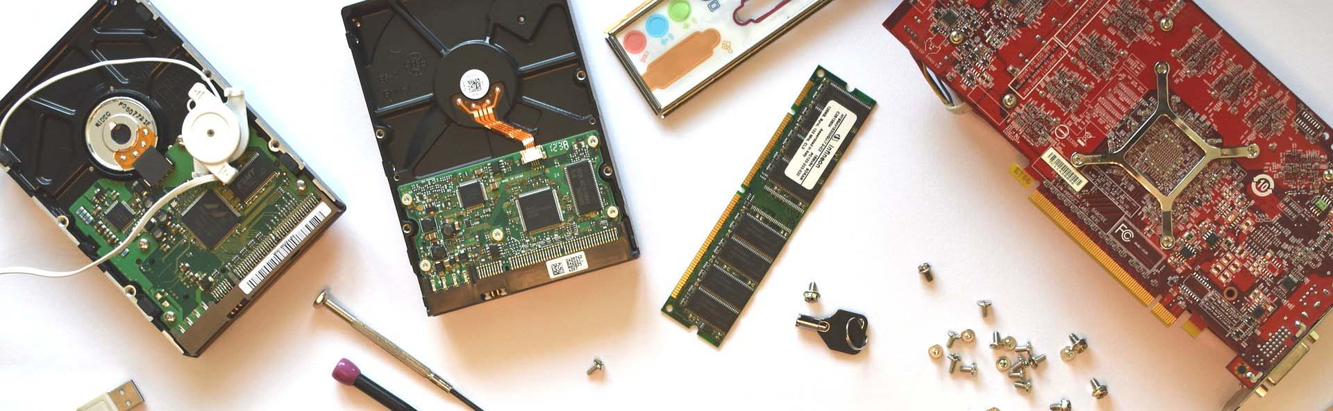
An import step in the PCB assembly process is placing the components on the board and for Surface Mount Devices (SMD) this is done with an automated Pick & Place machine.
SMT (surface mount technology) component placement systems, commonly called pick-and-place machines or P&Ps, are robotic machines which are used to place surface-mount devices (SMDs) onto a printed circuit board (PCB). They are used for high speed, high precision placing of broad range of electronic components, like capacitors, resistors, integrated circuits onto the PCBs which are in turn used in computers, consumer electronics as well as industrial, medical, automotive, military and telecommunications equipment.
Using automated Pick & Place machines is much faster and more accurate than a manually placement of the surface mount components.
Such machine have automated registration and super fast component placement with built in checks that use a variety of cameras.
Script – Pick & Place
For our Pick & Place machine to populate an assembly, we need some advanced preparation.
1.we upload the population program to the Pick & Place machine – this is based on the board layout – the BOM (bill of materials) and CPL (Component Placement List, also known as the Pick & Place file).We also load the Pick & Place with previously kitted components.
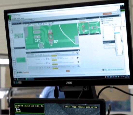
Figure 1:Upload the population program to the Pick & Place machine
2.The boards are printed with solder paste(Figure 2:Solder paste) and the paste deposit is inspected by our Automatic Solder Paste Inspection machine (Figure 4)also known as SPI.
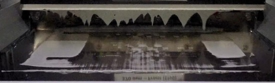
Figure 2:Solder paste
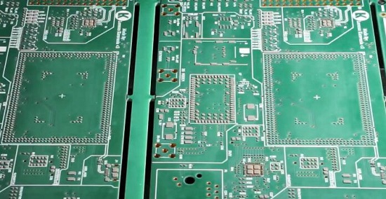
Figure 3:PCB boards with solder paste printed
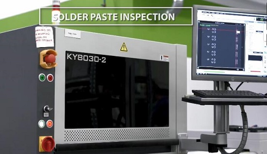
Figure 4: Automatic Solder Paste Inspection machine
3. trays have fixed outer dimensions, but the inside layout can vary based on the part. Our machines can manage up to 8 of these trays at a time.
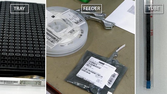
Figure 5:Tray,Feeder,Tube
Remark:Surface mount devices or SMD component parts usually arrive in tape, tube or tray format.
*For tape components we use feeders, different size feeders for different width tapes.
*The feeder magazine has a small pin which indexes the tape to the next position to present the next component for pick up.
*Tubes go into a “shaker”, which shakes the component inside the tube forward to the correct pick up position.
All the feeders, tubes and trays have an identification chip and a barcode.
Components get a unique identification barcode which contains a lot of information about the component including the (Manufacturers Part Number) MPN, quantity and size and other geometric and electrical information.The barcodes of components and feeders are linked together during the kitting process. We can place these parts anywhere on the machines, the chip in the feeder tells the machine which component is where.
Placement accuracy is essential and the Pick & Place machine uses 3 fiducial points to locate the panel and determine the orientation.
If there are multiple boards on one panel, each individual PCB has its own local fiducials. The fiducials are optical targets that are etched in the copper layer of every board.
The Pick & Place machine has a single pick up head and multi-head mounter. The single head is slower, but can grab different shapes and heavy parts. A multi-head can grab 8 parts at a time and thus mounts faster. Our engineers select the correct pick up head to be used based on the shape and weight of the parts, and the machine follows these instructions automatically during the assembly process.After picking up a component the optical centring camera of the machine takes a picture of the part, whilst moving it towards the mounting area.
The Pick & Place then automatically identifies the leads of the part, the dimensions, the rotation and places the part on the correct position defined by the X and Y coordinates of the CAD program.The Pick & Place machine can also measure resistance, capacitance, and inductance of the component all “on-the-fly”. These measurements make the process slightly slower, but increase the accuracy and avoids mistakes, a critical point when you produce prototype assemblies.
During the assembly process, the Pick & Place machine keeps different logs that we can analyse later.
These logs contain a huge range of information including mounting time, speed, pick errors, mount errors, head usage, we can even check kitting information and machine errors too. The Pick & Place machine also registers the program used for every order. The most common error is an identification error, when the machine fails to identify the component from underneath using its camera. We can improve the success rate with light settings or with reteaching the component to the machine. Sometimes the parts get stuck in the feeders or tubes so that the machine cannot pick them up. In that case we need to manually remove the parts, and adjust the component feed for the machine to pick up again.
We also get errors when the correct pick-up head is not selected, or when fiducials are not detected. Our machine operators are there to solve these kind of errors.
Back to the technology data
PCB Blog
Contact Us
E-mail: [email protected]
E-mail: [email protected]
Skype: [email protected]
Whatsapp: +86 15012972502
Add: 2F, BUILDING H, WANDA INDUSTRIAL ZONE, ZHOUSHI ROAD, LANGXIN COMMUNITY,SHIYAN STREET, BAO 'AN DISTRICT, SHENZHEN, GUANGDONG, CHINA


 Skype Chat
 WhatsApp
  Mail inquiry